
loading

Global Cooling Solution Provider And Manufacturer

In-rack manifolds are the supply & return distribution backbone inside each liquid-cooled rack. It delivers chilled coolant to server cold plates and collects the return.

1

Supply Manifold

Chilled coolant arrives from the CDU and enters the supply manifold.

→
2

Port → QD → Hose → Cold Plate

At each port, a non-spill quick disconnect (QD) connects a flexible coolant hose that feeds the server cold plate on the GPU or CPU.

→
3

Return Manifold

Warmed coolant exits each cold plate and enters the return manifold and flows back to the CDU for re-cooling.

Two-stage Liquid Cooling Distribution: In-Row Manifold & In-Rack Manifold

In a typical D2C (Direct-to-Chip) liquid cooling system, the In-Row Manifold serves as the row-side main manifold. It receives coolant from the CDU and distributes supply/return ports to every rack in the row.


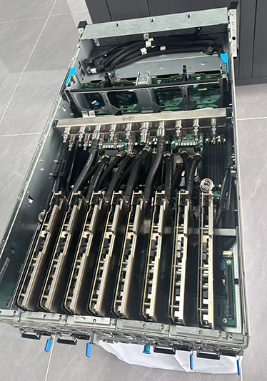
Mounted inside each rack, our In-Rack Manifold taps off the fluid circuit from the In-Row Manifold. It further divides the flow into dedicated branches for GPU / CPU cold plates inside the cabinet. Quick-disconnect fittings integrated on the In-Rack Manifold allow individual servers to be removed without draining the In-Row manifold’s row-level piping loop.


This hierarchical design reduces flow imbalance, simplifies leak containment, and lowers downtime during hardware replacement.
Two-stage Liquid Cooling Distribution: In-Row Manifold & In-Rack Manifold

In a typical D2C (Direct-to-Chip) liquid cooling system, the In-Row Manifold serves as the row-side main manifold. It receives coolant from the CDU and distributes supply/return ports to every rack in the row.


Mounted inside each rack, our In-Rack Manifold taps off the fluid circuit from the In-Row Manifold. It further divides the flow into dedicated branches for GPU / CPU cold plates inside the cabinet. Quick-disconnect fittings integrated on the In-Rack Manifold allow individual servers to be removed without draining the In-Row manifold’s row-level piping loop.


This hierarchical design reduces flow imbalance, simplifies leak containment, and lowers downtime during hardware replacement.

The Parameter of Lori Standard In-Rack Manifold

Lori offers standard In-rack manifold (All models share a 392 × 2371 × 194 mm body). Below are the parameters of the standard in-rack manifolds. If you need customized rack manifolds, please contact us promptly.


ModelCoupling ID
Port Quantity
 Rack Size Compatibility Inlet Position
LR112 / RM113 / RM1143 mm48 / 42 / 3652U / 48U·52U / 42U·48U·52UTop or Bottom
LR122 / RM123 / RM1246 mm48 / 42 / 3652U / 48U·52U / 42U·48U·52UTop or Bottom
LR132 / RM133 / RM1349 mm48 / 42 / 3652U / 48U·52U / 42U·48U·52UTop or Bottom


Chat Online 编辑模式下无法使用
Leave Your Message inputting...