With the continuous development and popularization of new energy vehicles in China, the demand for water-cooled aluminum alloy motor housings for new energy vehicles is also expected to increase. Today, we will discuss the processing and manufacturing technology of water-cooled motor housings and the solutions available.
Water-Cooled Motor Housing Process Analysis
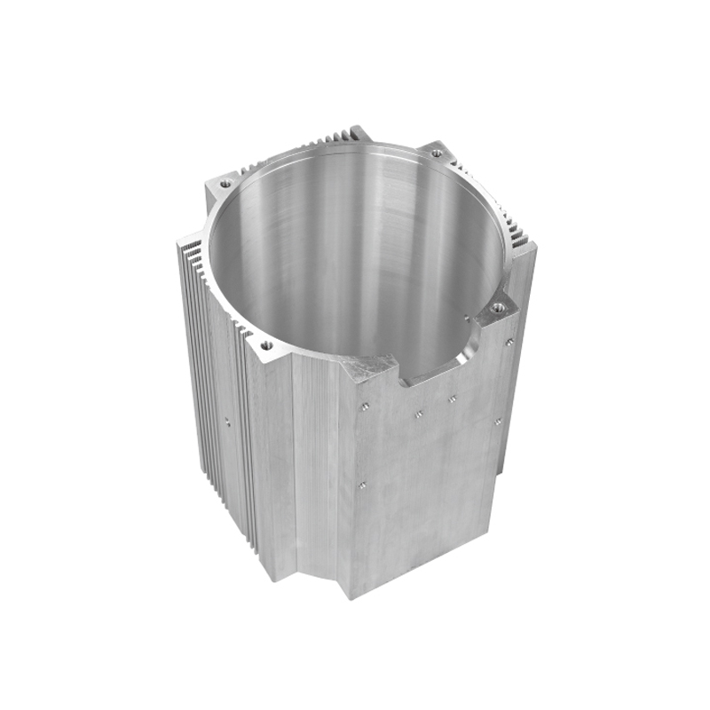
Most people are familiar with the heat dissipation principle of water-cooled motor housings. The manufacturing processes mainly include profile and die-casting methods.
1. Profile Water-Cooled Motor Housing: This method uses a profile process to create a flow channel. Cross-milling is then used on both sides to form the water circulation channel. An aluminum seal is used to cover and seal the channel. The profile is then joined by friction stir welding to form a sealed water circulation chamber. This process is relatively simple, but the channel structure is limited, resulting in average heat dissipation performance.
2. Die-Cast Motor Housing: Traditionally, die-cast motor housings have through-hole structures. However, more and more manufacturers are adopting integrated motor housings. The die-cast motor housing consists of an outer shell and a water jacket. The water jacket is typically designed with a spiral flow channel, and the shell is combined with the water jacket through machining and thermal sleeve processes, then sealed using friction stir welding to create a sealed flow channel chamber.
While integrated die-casting has become an industry trend, it has been plagued by a significant processing challenge: the issues of shrinkage cavities and porosity in die-casting materials, which result in high scrap rates. To address this, we collaborated with die-casting manufacturers to pioneer the development of a semi-solid die-casting process for motor housings. This process combines a semi-solid die-cast water jacket with a high-pressure die-cast outer shell and friction stir welding to effectively solve the issues of die-cast motor housings at minimal cost.
Why is Friction Stir Welding Favored for Water-Cooled Motor Housings?
Water-cooled motor housings require high leak-tightness and minimal deformation in the weld seams. Traditional fusion welding methods often face issues such as large deformations and hidden pores, which can compromise the safety performance of water-cooled motor housings. Friction stir welding, a solid-state welding technique, offers superior weld quality with minimal deformation, making it the best choice for water-cooled motor housings.
How to Select Friction Stir Welding Equipment for Motor Housings?
The most critical factor in selecting friction stir welding equipment for motor housings is to ensure that the Z-axis space height is sufficient. Specifically, the Z-axis space height must be greater than the height of the motor housing plus the length of the stir welding head and tool holder.
1. For Through-Hole Motor Housings: The height is generally around 200 mm, plus an internal support fixture height of about 200 mm, and the length of the tool holder and stir welding head (at least 160 mm), making a total height of more than 560 mm. Therefore, the Z-axis space height of the equipment needs to exceed 600 mm.
2. For Integrated Die-Cast Motor Housings: The height is generally around 320 mm, plus a contour support block of about 40 mm, and an extended tool holder and stir welding head of nearly 300 mm, making a total height of more than 650 mm. Hence, a Z-axis space height of 700 mm is recommended.
Currently, our standard friction stir welding equipment offers two Z-axis space options: 500 mm and 700 mm. Small models only have the C-type gantry machine with a 700 mm height, while medium-sized gantry machines mostly have a 500 mm height. Large gantry machines are generally overkill for motor housing welding. Therefore, we recommend the compact and cost-effective C-type gantry machine, which offers a flexible Z-axis space of either 500 mm or 700 mm, providing versatile and efficient welding solutions. The specifications are as follows:
Why Recommend Automatic Fixtures for Motor Housing Friction Stir Welding?
In water-cooled motor housings, the weld seam is located on the edges of the shell, which makes clamping and positioning difficult. Simple fixtures such as clamps or vices are not sufficient. Manual fixtures can be costly and inefficient for mass production. For batch production, it is better to use automatic fixtures, which offer higher efficiency and stable welding performance.
Through-Hole Motor Housing Fixture Options: Internal expansion type or external clamping type.
Integrated Motor Housing Fixture Options: Contour support + Adjustable clamping.
Key Considerations for Friction Stir Welding of Motor Housings
1. Surface Oxidation: The oxide layer on the weld surface needs to be removed, and a machining allowance of approximately 1 mm should be left on the surface.
2. Weld Gap: Ensure the gap between the welding surfaces is less than 0.2 mm, and the height difference is less than 0.3 mm.
3. Distance from the Edge: The distance from the edge of the weld seam should be at least 6 mm to avoid deformation. Special fixtures may be needed to control this, adding to process complexity.
4. Profile Motor Housing Design: The aluminum seal design should include a 0.5~1 mm overlap step to withstand the pressure from the stir welding head.
5. Design for Error Prevention: It is recommended to add positioning pin holes in the motor housing design.
6. Welding Path and Tail Hole Planning: The welding path and tail hole locations should be planned in advance.