As power electronics technology advances, wind energy converters are becoming increasingly integrated and powerful. The power and heat flux per unit volume are rising, necessitating enhanced heat dissipation capabilities. Traditional forced air cooling is insufficient to address the overheating issues. Research indicates that when the temperature of electronic devices reaches 70°C to 80°C, a 1°C increase can reduce their reliability by 5%. Therefore, converters with more than 2MW power require water-cooled systems for effective heat dissipation. The core heating component in these converters is the Insulated Gate Bipolar Transistor (IGBT), which primarily relies on liquid-cooled plate-type radiators.
The superior heat dissipation performance of liquid cooling plates is heavily influenced by the design of their internal flow channels. Various internal flow path structures are available on the market, each designed to optimize the heat dissipation characteristics of IGBTs. This article describes the heat dissipation effects, advantages, and disadvantages of different flow path designs. It aims to provide a reference for selecting and designing liquid cooling plates for effective thermal management in high-power converters.
1. Heat Dissipation Process Analysis
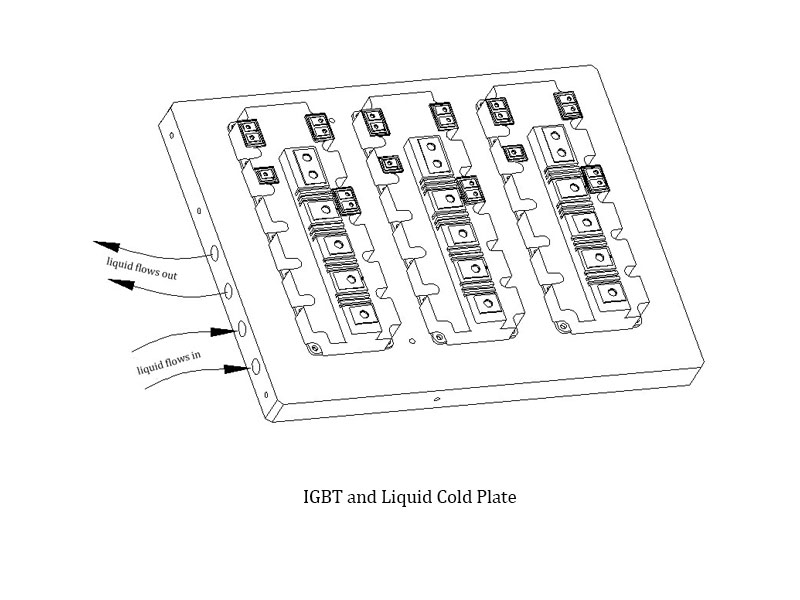
Heat transfer occurs through three mechanisms: radiation, conduction, and convection. The arrangement of the IGBT and water-cooled radiator is depicted in the figure. Heat is transferred from the IGBT to the water-cooled radiator primarily through conduction. The effectiveness of the IGBT radiator depends on the heat-carrying capacity of the water-cooled radiator. Once heat is transferred to the water-cooled radiator, the coolant flows through its internal channels, carrying away the heat via convection, thus achieving effective heat dissipation.
When the temperature rise stabilizes, we can disregard the minor amounts of heat lost through convection and radiation to the air. According to the conservation of energy and the laws of thermodynamics, the heat energy removed by the coolant per unit time should equal the heat energy emitted by the IGBT. This relationship can be expressed with the following simple formula:
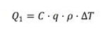
Where:
Q1 is the heating power consumption per unit time, in Joules (J).
C is the specific heat capacity of the coolant, in Joules per kilogram per degree Celsius (J/(kg·°C)).
q is the coolant flow rate, in cubic meters per second (m³/s).
ρ is the coolant density, in kilograms per cubic meter (kg/m³).
is the temperature difference between the inlet and outlet of the radiator, in degrees Celsius (°C). - 
In the above formula, Q1represents the heating power consumption per unit time, which is equivalent to the heat flow Q2transferred between the water-cooled radiator and the coolant. According to Newton's law of cooling, this can be expressed as:
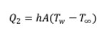
Where:
Q2 is the heat flow rate between the coolant and the radiator, in Watts (W).
h is the convective heat transfer coefficient, in Watts per square meter per degree Celsius (W/m²·°C).
A is the heat dissipation area in contact with the coolant, in square meters (m²).
is the wall temperature of the radiator, in degrees Celsius (°C).-
is the temperature of the coolant, in degrees Celsius (°C).-
The water-cooled cooling system of the converter is a closed system. When designing the cooling capacity, the system's total heating power consumption is considered first. The coolant flow rate q is then estimated using the formula:
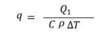
is typically 5°C, and C is related to ρ and the coolant, which is usually a glycol-water solution. Once the flow rate is determined, the overall heat dissipation capacity of the system is set.
To ensure the inlet and outlet temperature difference meets the required 5°C, the heat flow Q2 between the coolant and the water-cooled radiator must be optimized. According to the formula:
The efficiency of heat transfer can be enhanced by increasing the heat transfer coefficient h and the contact area A. The heat transfer coefficient is influenced by factors such as the material and the type of coolant used. Typically, the heat dissipation area A is increased and turbulence within the flow channels is enhanced to reduce thermal resistance, thereby improving the convective heat transfer coefficient. This approach ultimately achieves optimal heat dissipation.
2. Structural Comparison of Typical Flow Channels
Water-cooled radiators come in various designs, and there is no universally accepted classification standard. For instance, based on the flow channel layout, radiators can be categorized into series and parallel structures. If we consider the arrangement, they can be classified into aligned finned and staggered finned structures. This paper introduces several commonly used runner structures in the converter industry, providing a reference for designers in runner design.
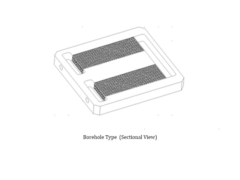
2.1 Borehole
The internal cross-sectional structure of a borehole type water-cooled radiator is illustrated in Figure. This radiator features a straight, round flow channel, with each branch forming a typical parallel structure. The cooling medium enters from one side and flows out from the other. The borehole runner has several advantages: it has a simple structure, is easy to process, requires minimal installation effort, and allows devices to be mounted on both sides.
However, this structure has limitations. Its size is constrained, intersecting flow channels can only form right angles, and it has high local flow resistance. The cross-sectional shape is uniform, the thermal resistance is relatively high, and sealing is challenging. According to equation (2), optimizing this runner structure involves adjusting the diameter of the circular channels and the number of parallel connections based on the heating power in practical applications to achieve the optimal values for h and A, thereby enhancing heat dissipation efficiency. Due to its low production cost and simple design, this type of radiator is suitable for low-power applications.
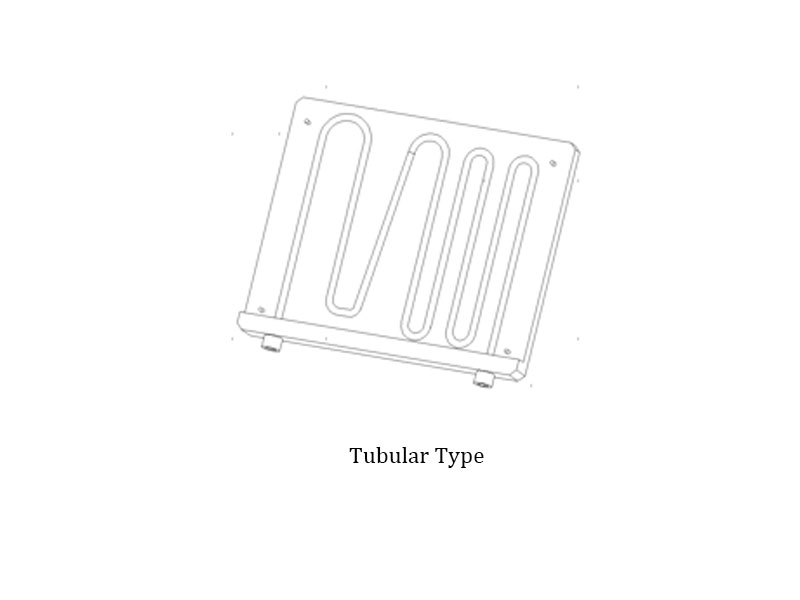
2.2 Tubular Type
A tubular radiator consists of a copper tube bent back and forth and embedded in the mounting surface of the radiator device. The cooling medium flows in from one end of the copper tube and exits from the other. This flow channel structure offers several advantages: low structural cost, a simple manufacturing process, and long-lasting corrosion resistance of the pressure nozzle.
However, this design has significant drawbacks. It has high thermal resistance, a large turning radius, and increased pressure loss, which lowers overall performance. The layout of the copper pipes also affects device installation, limiting its use to low thermal power consumption equipment.
In this design, grooves are milled into an aluminum plate, fins are placed within the grooves, and the plate is then welded and sealed. The inlet and outlet of the flow path are designed according to actual needs, with the fins positioned directly beneath the heating device. The addition of the fin structure significantly increases the heat exchange surface area between the cooling medium and the fins.
According to equation (2), adding fins enhances fluid disturbance, thereby increasing the convective heat transfer coefficient (h). Additionally, the heat transfer area (A) is greatly expanded, increasing by more than ten times compared to the previously described flow channel. Although this increases system resistance, the excellent heat dissipation makes this type of radiator widely used in the heat dissipation systems of wind energy converters.
2.3 Milling Groove Type
This type of flow channel is created by milling grooves on an aluminum plate. The design of these flow channels is highly flexible and can be tailored to the specific heat dissipation needs of the device, balancing flow resistance and thermal resistance.
In this runner design, the heat transfer area (A) can be increased by adjusting the diameter, density, and turning angle of the grooves. Optimal heat transfer efficiency is achieved by enhancing fluid disturbance and increasing the heat transfer coefficient (h). Due to its high heat transfer efficiency, low risk of clogging, and flexible design, this type of radiator is widely used in high-power converter heat dissipation systems.
Analyzing the commonly used radiator runner structures in the market reveals that optimal designs focus on maximizing the heat exchange area. To address the trend of increasing heat flow density, Lori’s technical experts have been exploring more cutting-edge special flow channel structures. These include combinations of different flow channel types, micro-channels, and direct contact flow channels, to further enhance performance.
3. End
Through our analysis of the heat dissipation process of IGBT water-cooled radiators in converters, we recognize the significant impact of the internal flow structure on heat dissipation effectiveness. As heat flux continues to rise, there is a growing demand for more efficient water-cooled radiators in the market.
Lori specializes in the development and production of water-cooled radiators. We have rich experience in heat dissipation design and provides customized production services to address your heat dissipation challenges in one stop. Contact us today for all your cooling needs!