Photovoltaic inverters are crucial components in photovoltaic systems. Their primary function is to convert the direct current (DC) generated by photovoltaic modules into alternating current (AC). In addition, inverters perform important functions such as monitoring the status of modules, the grid, and cables, facilitating communication with external systems, and ensuring system safety. A new inverter can take over two years from development to mass production. Besides over-voltage and under-voltage protection features, inverters include many lesser-known advanced technologies such as leakage current control, heat dissipation design, electromagnetic compatibility, harmonic suppression, and efficiency control, all of which require significant investment in research and testing.
This article mainly introduces the heat dissipation design technology of inverters.
1. Why Heat Dissipation is Needed for Inverters
In the cold winter season, many people worry about whether inverters can withstand freezing temperatures. In reality, inverters rarely get damaged from freezing. The most critical issue is heat. According to a renowned global survey by BCC, 55% of electronic product failures are due to poor heat dissipation. The reliability of electronic components is highly sensitive to temperature; for every 1°C increase in component temperature from the 70-80°C range, reliability decreases by 5%. Excessive temperatures can shorten the lifespan of inverters and reduce machine reliability.
2. Types of Heat Dissipation Methods for Inverters
The heat dissipation system accounts for about 15% of the hard cost of inverters. It mainly includes heat sinks, cooling fans, thermal grease, and other materials. Currently, there are two main heat dissipation methods for inverters: natural convection and forced air cooling.
Natural Convection
Natural convection is a cooling method that does not use any external auxiliary energy to dissipate heat from the heat-generating components to the surrounding environment, relying on conduction, convection, and radiation. This method mainly uses natural convection. Natural convection or cooling is often used for low-power devices and components with low heat flux density where temperature control requirements are not high. Most single-phase inverters and three-phase inverters below 30kW can achieve natural convection cooling, and a few manufacturers can even achieve natural convection for 100kW three-phase inverters.
Forced Air Cooling
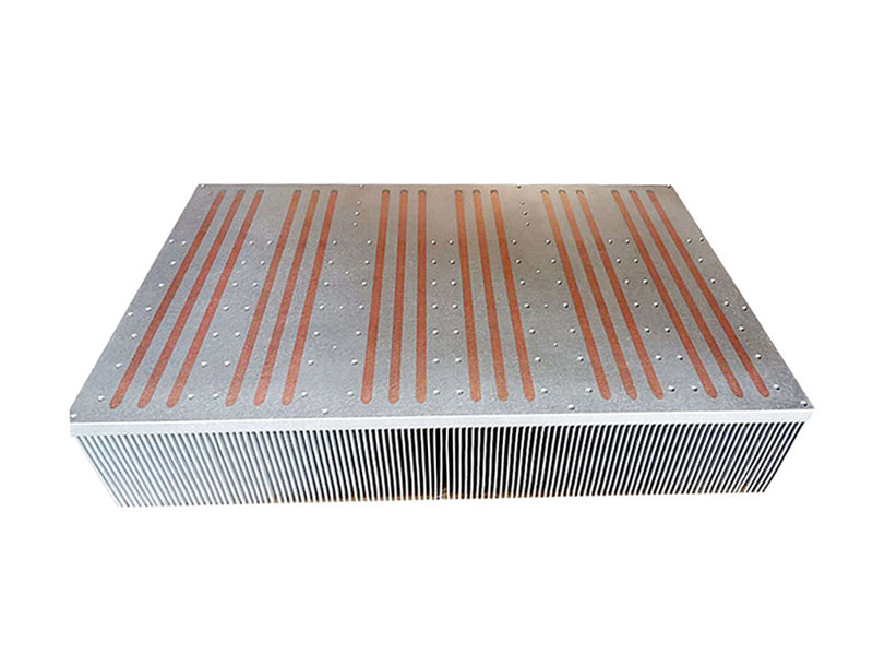
Forced air cooling relies on fans or other means to enhance air circulation around components to carry away the heat generated. This method is simple to operate and shows obvious results. If the spacing between components allows for good air flow or suitable installation of localized heat sinks, this cooling method can be employed. To improve forced convection heat transfer capability, increasing the heat sink area and generating a significant forced convection heat transfer coefficient are essential. Heat sinks with expanded surfaces, made through folded fins or stamped thin fins, are widely used. The choice of material for heat sinks, such as copper or aluminum, directly affects their performance.
Comparison of the Two Methods
Natural convection, without fans, produces low noise but has slower cooling speeds and is generally used for low-power inverters. Forced air cooling requires fans, which produce noise but offer faster cooling, and is typically used for high-power inverters. For medium-power string inverters, both methods can be employed. Experimental comparisons of string inverter cooling capabilities show that for inverters with power ratings above 50kW, forced air cooling is more effective than natural convection, reducing the temperature rise of key components like capacitors and IGBTs by around 20°C, ensuring long-lasting and efficient operation. Forced air cooling can use high-speed or medium-speed fans; high-speed fans reduce the heat sink's size and weight but increase noise and have shorter lifespans. Medium-speed fans are larger, operate at low speeds at lower power, and their lifespan is longer, as inverters rarely run at full power continuously.
3. Inverter Heat Dissipation Design
The primary tasks of an inverter heat dissipation system are to: select appropriate heat dissipation and cooling methods, design an effective cooling system, control the temperature of electronic components within specified limits, and provide a low thermal resistance pathway between the heat source and the external environment to ensure effective heat dissipation.
Heat Loss Calculation
To design a heat dissipation system, first calculate the heat generated by the inverter. The main sources of heat are power switch transistors, filter inductors, and transformers. The efficiency of transformers and inductors can be customized with manufacturers. The power switch transistor losses can be calculated using software simulations, depending on output current, DC voltage, power factor, overload factor, modulation index, and output frequency.
Cooling Method Selection
The heat design of electronic equipment starts with determining the cooling method. The selection should consider heat flux density, temperature rise requirements, reliability, size, weight, cost, and safety. For higher heat flux densities and temperature rise requirements, adding heat sinks and forced air cooling is effective. Forced air cooling is reliable, easy to maintain, and relatively low in cost, making it widely adopted in electronic devices needing cooling, especially for high-power components.
Thermal Design Steps
For forced air cooling designs involving heat sinks, the steps include:
A. Considering factors like equipment structure, wind pressure, cost, and cooling efficiency, and using thermal simulation software to determine heat sink structure parameters.
B. Based on heat generation and thermal balance equations, preliminarily select a fan.
C. Perform thermal design using the fan and a well-designed airflow pathway.
D. Use thermal simulation software to validate the design; if the final component temperatures exceed acceptable values, adjust the heat sink structure parameters, select a different fan, and repeat the steps. The goal is to keep component temperatures within allowable limits and optimize the cooling system.
Heat Sink Design
Heat sink design should consider structural requirements, cost, wind pressure, cooling efficiency, and manufacturing processes. Fins should be thin but not so thin that they are difficult to process. For a given heat sink size, smaller fin spacing reduces thermal resistance but may increase airflow resistance. Increasing fin height can enhance the heat dissipation area but does not necessarily increase heat transfer beyond a certain point, as it can reduce efficiency and increase airflow resistance.
System Airflow Design
Basic principles for airflow design include:
A. Maximizing the airflow and speed through the heat sink fins to improve cooling performance.
B. Minimizing airflow resistance to prevent excessive pressure losses.
C. Ensuring that hot air flows are smoothly expelled from the exit duct.
Thermal Design Simulation
Thermal simulation software can realistically model the system's thermal behavior, allowing for predictions of component temperatures during the design process. This helps correct layout issues, reduce design cycles, lower costs, and improve the first-time success rate. Effective thermal control ensures electronic devices operate within specified temperature limits, enhancing reliability.
4. Latest Heat Dissipation Technologies for Inverters
With advances in electronics, inverters have made significant progress in heat dissipation, allowing for smaller, lighter, and more affordable designs.
Multi-Level Technology: Higher voltages increase internal resistance and switching losses. Recent multi-level technologies (three-level, five-level) reduce voltage to half or a quarter of two-level structures and also lower switching frequencies, thus reducing losses.
Soft Switching Technology: Utilizing resonance principles, soft switching reduces switching losses by ensuring current or voltage changes according to sinusoidal or quasi-sinusoidal patterns. This reduces switching losses and addresses issues like inductive turn-off and capacitive turn-on.
Cavity Management: Sensitive components like sensors, op-amps, and electrolytic capacitors are affected by temperature. Power switch transistors, inductors, and cables tolerate higher temperatures. Cavity management isolates heat-generating components by placing them outside the inverter to lower internal temperatures. Integrated shell structures and direct connection of heat sinks to the outer casing help reduce internal and component temperatures, extending their lifespan.
New Materials: Utilizing materials like silicon carbide (SiC) in IGBTs allows for lower internal resistance, reducing losses.
5. Considerations for Heat Dissipation During System Installation
Inverters generate heat and must dissipate it effectively. They should not be placed in enclosed spaces where temperatures could rise. Inverters should be installed in well-ventilated areas and kept out of direct sunlight. When multiple inverters are installed together, sufficient spacing should be maintained between them to avoid mutual interference.
Lori focuses on providing advanced thermal solutions. We have a professional thermal design and R&D team, equipped with advanced design software and quality testing systems. Lori is a high-tech enterprise specializing in high-power thermal management solutions, offering one-stop thermal management services. Contact us if needed!